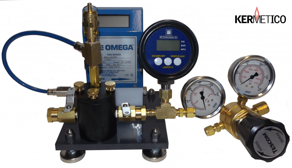
We have designed our Coating Gas Permeability Tester to measure the degree of gas permeation through a coating due to the coating through porosity and other interconnected defects.
Conventional methods for the evaluation of thermal spray coating porosity are qualitative.
A metallographic porosity check is quite long, expensive and is a subject to mistakes due to poor specimen preparation or interpretation.
The quantitative gas permeability test allows one to measure porosity in minutes, even in field conditions.
Do you want to know the best part?
You do not need to machine samples after spraying them.
You do not need electricity, glue, polishing materials, etc.
Just the sample disc and nitrogen.
The Procedure for Gas Permeability Testing
The process is easy:
- Spray the sample disc
- Test for gas permeability
- Calculate the result
- Save the sample for the future reference
The Principle of Coating Gas-Permeability Testing

The Kermetico Gas Permeability Tester
According to ISO 4022, gas permeability is the ability of a porous metal to pass a fluid under the action of a pressure gradient.
The method we use is based on the measuring of a volumetric flow rate of the test gas passing through the coating of known thickness under a controlled pressure drop.
The Presentation of Results
- Total flow rate Q at fixed pressure drop DP for a fixed coating thickness
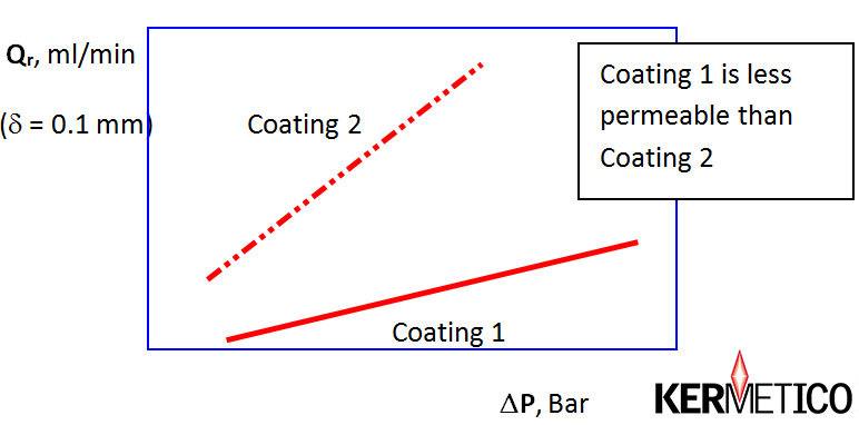
- Plotting of the graph “Gas flow rate Qr versus pressure drop DP”
The flow rate Q through the sample of known thickness (or the flow rate Qr, reduced to the standard sample thickness, for example, 1 mm, 0.1 mm, etc.) is plotted against the pressure drop DP. This graph is a final result of the measurements:

A Graphical Presentation of Gas Permeability Measurement Results
Calculating the Coefficient of Viscous Gas Permeability
The calculation is based on the following assumptions. For gaseous fluids and materials with very small pore size, the inertia flow is negligible, and the flow is regarded as strictly viscous when Darcy’s law applies [2]:
DP / d = Q * h / (A * Y n) , (1)
or
Y n / d = Q * h / (A * DP)
where:
- DP is the pressure gradient (Pa);
- d is the thickness of the test piece (m);
- A is its cross-sectional area (m2);
- h is the dynamic (absolute) viscosity of the test fluid (Pa * s);
- Q is the volumetric flow rate of the fluid (m3 / s);
- Y n is the viscous permeability coefficient (m2).
The viscous permeability coefficient Y n has the physical meaning of the area of through pores in a 1 m2 sample. In the Q – DP graph, it is the tangent of the line slope.
It is convenient to present the results of Y n measurement in square nanometers (nm2).
The Gas Permeability Measurement Procedure
The coating sample of 50-600 microns (2-24 mils) thickness is sprayed onto a porous stainless steel disc (25 mm (1”) diameter, 3 mm (1/8”) thick, 2-micron average pore size).
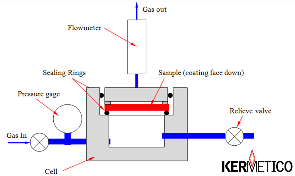
Both sides of the sample are sealed with rubber O-rings (grease the O-rings for each measurement), forming a 19 mm (3/4”) diameter open (working) area, the coating sample is placed into the tester cell (coating face down). Nitrogen under controlled pressure (0.01 – 21.00 Bar- 0.15- 305 PSIG) is introduced into the cell under the coating, while the gas flow rate is measured above the coating (Fig. 2). The dependence of gas flow rate trough the coating on the cell pressure plotted as a graph, characterizes the coating gas permeability.
The flow rate is calculated for 1 cm2 area and similar coating thickness for compared samples. The recommended coating thickness is about 0.05-0.10 mm (0.002”-0.004”) for dense coatings, and about 0.4 mm (0.016”-) for porous coatings. Coating thickness must be measured with a micrometer to use its value in the calculations.
The viscous permeability coefficient Y n (nm2) is calculated from (1) as:
Y n = 7783 Q * d / DP,
where:
- Q is flow rate, cm3/min (ml/min)
- d is coating thickness, cm
- DP is gas pressure drop, Bar
assuming, the sample area is 2.3 cm2; m (gas dynamic viscosity) =0.0179 cp = 1.79 * 10-5 Pa * s (for air and nitrogen).
Alternatively, total flow at a fixed testing pressure drop and a fixed coating thickness is used as a quick reference for coating quality control.
Two flowmeters are supplied for measurements with the standard Gas Permeability Tester:
- HVOF and HVAF coatings: full scale 5.6 ml/min for nitrogen
- Plasma and electric arc sprayed coatings: full scale 51.0 ml/min for nitrogen.
Permeability Testing Results Presentation
The results are presented as one of the following:
- total gas flow rate Q (ml/min) at fixed pressure gradient DP (Bar) (for instance, for quality control purposes)
- the graph of the gas flow rate Q (ml/min) versus the pressure gradient DP (Bar) for a 1 cm2 coating area and 0.1 mm (0.004”) coating thickness;
- the viscous gas permeability coefficient Y n (nm2).

Scheme of the Device
Fig.2. The Scheme of the Device for a Coating Gas-Permeability Measurement
The Price of Gas Permeability Tester: USD2,900 EXW Benicia, CA.
Kermetico, Inc. – HVAF Equipment Design and Manufacture since 2006
We make different spray guns for different applications. Please check the full spectrum of our equipment here. Our HVAF systems operate each of our guns or several guns at once (by request).
We proudly design and produce our HVAF thermal spray equipment in California, USA, and install it all over the world. You can visit our R&D center in Benicia to meet our designers and see our HVAF equipment in action.
Kermetico Inc. designs and manufactures three families of HVAF thermal spray equipment
- Convertible HVOF and HVAF equipment:
- Multi-purpose HVAF AK systems, with a variety of spray guns:
- AK7 – a high power gun for the thermal spray of large parts
- AK6 – a universal gun to spray a balanced mix of parts in a job shop
- AK5 – a compact gun to spray smaller parts, thin walls and complex surfaces
- AK-ID – an 88 mm (3.47”) and larger internal diameter spray gun
- AK-IDR – a rotating ID gun to spray 4” (100 mm) and larger bores
- AK-HH – a handheld gun for on-site coating
- Specialized HVAF S equipment:
- Additional equipment:
- An HVAF grit feeder for the grit blast preparation of parts to reduce coating costs


